Channels
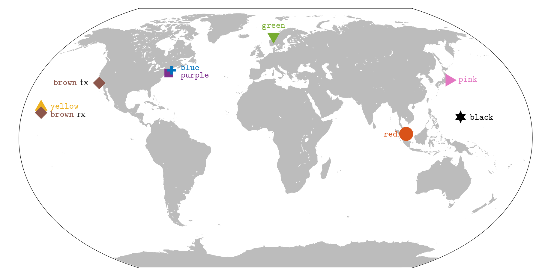
The channels contained in this library come from various experiments. The experiments differ by geographical location, transmission distance, water depth, transmitter/receiver mobility, acoustic bandwidth, and the size of the recording array. The channels are color-labeled, and a detailed description of relevant parameters is given below for each. The channels are available for download from Zenodo:

The experiments, the channel estimation procedure, and the noise models are described in the accompanying paper, arXiv:2609.03207.
Each channel is estimated from the experimental data and stored as a tensor of complex-baseband impulse responses evolving over time, with dimensions [delay, receiver, time]. If a recording array is available, the tensor holds one matrix for each array element. Each column of this matrix is an instantaneous channel response as a function of delay, that is, the channel vector at time index . Successive columns correspond to different, equi-spaced instants in time. Any motion-induced delay drift is suppressed in the channel matrix, leaving the drift-free response , which compresses efficiently for storage. A separate vector, the phase estimate stored as phi_hat, is provided that contains the uncompressed time-varying channel phase, which is directly related to the delay drift. Here is the sampling interval along the delay axis. To fully reconstruct the channel, the stored matrix needs to be decompressed, and the phase/delay needs to be imparted to re-introduce the phase shift and the delay drift. Details of this process, along with the ready-to-use code, are given in the User’s Guide. The stored variable names, and the alternative convention in which only the phase is tracked (theta_hat) and the delay drift is left in the taps, are documented in the channel file format specifications.
| Codename | Location | Date | dT/dR/dw [m] | Mobility | d [km] | fc [kHz] | R [ksym/s] | Array | M | ℓ [m] |
|---|---|---|---|---|---|---|---|---|---|---|
| Blue | North Atlantic | Jun. 2010 | 30-60/50/100 | Mobile | 3-7 | 13 | 104/2048 | Vertical | 12 | 0.12 |
| Red | Singapore | Nov. 2024 | 6/4.6/8-20 | Drifting | 0.1-0.4 | 25 | 9.6 | Vertical | 3 | 0.8 |
| Yellow | Hawaii | Jul. 2011 | 50/50/100 | Moored | 3 | 13 | 6.25 | Vertical | 24 | 0.05 |
| 7 | 24 | 0.2 | ||||||||
| 50/8.6-65/100 | 3 | 16 | 3.75 | |||||||
| 7 | 16 | 3.75 | ||||||||
| Purple | North Atlantic | Oct. 2008 | 11/10/15 | Moored | 0.06 | 12.5 | 104/1536 | Cross | 32 | 0.0375 |
| 0.2 | Vertical | 24 | 0.05 | |||||||
| 1 | Vertical | 12 | 0.12 | |||||||
| Green | Norway | Nov. 2024 | 20/43/60 | Moored | 0.27 | 6 | 4.5 | Time | 64 | 10 min |
| Black | Mariana Trench | Oct. 2024 | 8718/6/8720 | Moored | 8.72 | 18 | 12.5 | Planar | 8 | ≥ 0.088 |
| Pink | Japan | Jul. 2022 | 176/146/x | Moored | 14 | 6 | 4 | Vertical | 24 | 0.9-1.8 |
| Brown | Pacific | Nov. 1994 | 652/900-1600/4000, 5300 | Mobile | 3250 | 0.075 | 0.0375 | Vertical | 20 | 35 |
Column key: dT, dR, and dw are the transmitter depth, the receiver depth, and the water depth; d is the transmitter-receiver distance; fc is the center frequency; R is the symbol rate of the transmitted probe signal; M is the number of array elements; ℓ is the inter-element spacing. Where two values are listed for dw, they are the water depths at the transmitter and at the receiver. An "x" marks a value that was not recorded.
For the Green channel, M denotes the number of time-diversity channels formed from repeated transmissions on a single hydrophone, and ℓ denotes the inter-transmission interval.